|
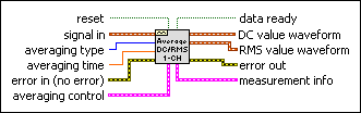
reset resets the history of your time signal. You typically use reset to reset the exponentially averaged measurement.
|
 |
signal in is the input waveform.
|
 |
averaging type is the type of averaging used during the measurement. If averaging type is exponential, this VI calculates the DC and RMS values using an exponentially weighted averaging measurement starting from the previous DC and RMS values.
| 0 | Linear—Averaging time is equal to the record length. | | 1 | Exponential—Time constant is half the record length. |
|
 |
averaging time defines dt of DC value waveform and RMS value waveform in seconds. The default is –1.00, which corresponds to average time = input block duration. For linear averaging, each output data point results from performing the averaging process for the time period specified by averaging time. For exponential averaging, each output data point results from exponential integration performed for the time period specified by averaging time using exp. time constant.
|
 |
error in describes error conditions that occur before this node runs. This input provides standard error in functionality.
|
 |
averaging control contains the advanced parameters used to completely control the DC or RMS measurement.
|
window for DC is the window to be applied to the time record before DC computation. LabVIEW ignores this input if averaging type is exponential.
| 0 | Rectangular (no window) | | 1 | Hanning | | 2 | Low side lobe |
|
|
output function selects the type of measurements to be performed. If you need only DC or RMS measurements, selecting these components separately increases the processing speed.
| 0 | DC only | | 1 | RMS only | | 2 | DC and RMS |
|
|
window for RMS is the window to be applied to the time record before RMS computation. LabVIEW ignores this input if averaging type is exponential.
| 0 | Rectangular (no window) | | 1 | Hanning | | 2 | Low side lobe |
|
|
exp. time constant specifies the time constant (RC) of your DC or RMS measurement. exp. time constant equals –1.00, which corresponds to a value of input block duration/2.
|
|
Set Ignore input start time to TRUE when you do not want the VI to check for continuity using t0 values.
|
|
 |
data ready indicates the DC value waveform and RMS value waveform contain data. A value of FALSE means the waveforms do not contain data.
|
 |
DC value waveform indicates DC values of signal in computed over averaging time seconds and time stamped continuously from the last reset.
|
|
RMS value waveform indicates RMS values of signal in computed over averaging time seconds and time stamped continuously from the last reset.
|
 |
error out contains error information. This output provides standard error out functionality.
|
 |
measurement info returns information about your measurement, mainly warnings for inconsistencies in your input signal.
 |
uncertainty is reserved for future use.
|
|
Warning is TRUE if a warning is generated during processing.
|
 |
comments contains a warning message when Warning is TRUE.
|
|
It is assumed that the array of input waveforms is the result of a multichannel acquisition where each element in the array of waveforms is a distinct and separate channel of data.
|
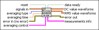
reset resets the history of your time signal. You typically use reset to reset the exponentially averaged measurement.
|
 |
signals in is the array of input waveforms.
|
|
averaging type is the type of averaging used during the measurement. If averaging type is exponential, this VI calculates the DC and RMS values using an exponentially weighted averaging measurement starting from the previous DC and RMS values.
| 0 | Linear—Averaging time is equal to the record length. | | 1 | Exponential—Time constant is half the record length. |
|
|
averaging time defines dt of DC value waveform and RMS value waveform in seconds. The default is –1.00, which corresponds to average time = input block duration. For linear averaging, each output data point results from performing the averaging process for the time period specified by averaging time. For exponential averaging, each output data point results from exponential integration performed for the time period specified by averaging time using exp. time constant.
|
|
error in describes error conditions that occur before this node runs. This input provides standard error in functionality.
|
|
averaging control contains the advanced parameters used to completely control the DC or RMS measurement.
|
window for DC is the window to be applied to the time record before DC computation. LabVIEW ignores this input if averaging type is exponential.
| 0 | Rectangular (no window) | | 1 | Hanning | | 2 | Low side lobe |
|
|
output function selects the type of measurements to be performed. If you need only DC or RMS measurements, selecting these components separately increases the processing speed.
| 0 | DC only | | 1 | RMS only | | 2 | DC and RMS |
|
|
window for RMS is the window to be applied to the time record before RMS computation. LabVIEW ignores this input if averaging type is exponential.
| 0 | Rectangular (no window) | | 1 | Hanning | | 2 | Low side lobe |
|
|
exp. time constant specifies the time constant (RC) of your DC or RMS measurement. exp. time constant equals –1.00, which corresponds to a value of input block duration/2.
|
|
Set Ignore input start time to TRUE when you do not want the VI to check for continuity using t0 values.
|
|
|
data ready indicates the DC value waveform and RMS value waveform contain data. A value of FALSE means the waveforms do not contain data.
|
 |
DC value waveforms is an array of waveforms containing DC values.
|
|
RMS value waveforms is an array of waveforms containing RMS values.
|
|
error out contains error information. This output provides standard error out functionality.
|
 |
measurements info is an array that returns information about your measurement, mainly warnings for inconsistencies in your input signal.
|
uncertainty is reserved for future use.
|
|
Warning is TRUE if a warning is generated during processing.
|
|
comments contains a warning message when Warning is TRUE.
|
|
This VI is designed to process a single channel or multiple channels continuously, typically from within a For Loop or a While Loop.
 Add to the block diagram
 Find on the palette