 |
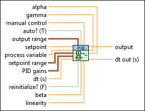
alpha specifies the derivative filter time constant. Increasing this value increases damping of derivative action. alpha can be a value between 0 and 1 or NaN, which specifies that no derivative filter is applied.
|
 |
gamma specifies an amount by which to weight the error applied to derivative action. The default value is 0, which avoids the derivative kick, or sudden change in controller output, that can occur after a change in the setpoint value.
In certain cascade control operations where derivative kick is not a concern, increasing gamma might improve the speed of the first PID controller.
|
 |
manual control specifies the value of the control output when auto? is FALSE.
|
 |
auto? specifies whether to use automatic or manual control. In some situations, you might need to switch off the PID controller and operate the system in manual, or open-loop, mode. The default is TRUE. When auto? is TRUE, this VI uses automatic control. When auto? is FALSE, this VI uses manual control. This VI uses bumpless transfer from manual control to automatic control.
|
 |
output range specifies the range to which to coerce the control output. The default range is –100 to 100, which corresponds to values specified in terms of percentage of full scale. You can change this range to something that is appropriate for your control system. For example, you can relate engineering units to engineering units instead of percentage to percentage. This VI implements integrator anti-windup when the controller output is saturated at the specified minimum or maximum values.
 |
output high specifies the maximum value of the controller output. The default is 100.
|
 |
output low specifies the minimum value of the controller output. The default is –100.
|
|
 |
setpoint specifies the setpoint value, or desired value, of the process variable being controlled.
|
 |
process variable specifies the measured value of the process variable being controlled. This value is equal to the feedback value of the feedback control loop.
|
 |
setpoint range specifies the maximum and minimum values for the setpoint/process variable range. This VI uses the setpoint range to calculate nonlinear integral action. The default range is 0 to 100, which corresponds to values specified in terms of percentage of full scale. You can change this range to something that is appropriate for your control system. For example, you can relate engineering units to engineering units instead of percentage to percentage. This VI uses the setpoint range in the nonlinear integral action calculation and the nonlinear error calculation.
 |
setpoint low specifies the minimum value of the setpoint/process variable range.
|
 |
setpoint high specifies the maximum value of the setpoint/process variable range.
|
|
 |
PID gains specifies the proportional gain, integral time, and derivative time parameters of the controller.
 |
proportional gain (Kc) specifies the proportional gain of the controller. The default is 1. In the equation that defines the PID controller, KC represents the proportional gain.
|
 |
integral time (Ti, min) specifies the integral time in minutes. The default is 0.01.
|
 |
derivative time (Td, min) specifies the derivative time in minutes. The default is 0.
|
|
 |
dt (s) specifies the loop-cycle time, or interval in seconds, at which this VI is called. If dt (s) is less than or equal to zero, this VI calculates the time since it was last called using an internal timer with 1 ms resolution. If dt (s) must be less than 1 ms, specify the value explicitly. The default is -1.
|
 |
reinitialize? specifies whether to reinitialize the internal parameters, such as the integrated error, of the controller. Set reinitialize? to TRUE if your application must stop and restart the control loop without restarting the entire application. The default is FALSE.
|
 |
beta specifies the relative emphasis of setpoint tracking to disturbance rejection. The default value of 1 is appropriate for most applications. You can use a smaller value between 0 and 1 to specify emphasis on disturbance rejection, such as process load changes. The VI uses this value in the two degree-of-freedom algorithm.
|
 |
linearity specifies the linearity of the error response. The valid range for linearity is 0 to 1. A value of 1 provides a normal linear response, while a value of 0.1 provides an approximately parabolic response. The VI uses this value in the nonlinear error calculation and the nonlinear gain factor calculation.
|
 |
output returns the control output of the PID algorithm that is applied to the controlled process. If this VI receives an invalid input, output returns NaN.
|
 |
dt out (s) returns the actual time interval in seconds. dt out (s) returns either the value of dt (s) or the computed interval if you set dt (s) to –1.
|
 |
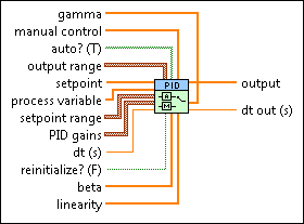
gamma specifies an amount by which to weight the error applied to derivative action. The default value is 0, which avoids the derivative kick, or sudden change in controller output, that can occur after a change in the setpoint value.
In certain cascade control operations where derivative kick is not a concern, increasing gamma might improve the speed of the first PID controller. This VI resizes the gamma input array to match the size of the process variable input array.
|
 |
manual control specifies the value of the control output when auto? is FALSE. This VI resizes the manual control input array to match the size of the process variable input array.
|
 |
auto? specifies whether to use automatic or manual control. When auto? is�TRUE, this VI uses automatic control. When auto? is FALSE, this VI uses manual control. This VI uses bumpless transfer from manual control to automatic control. The default is TRUE.
This VI resizes the auto? input array to match the size of the process variable input array.
|
 |
output range specifies the range to which to coerce the control output. The default range is -100 to 100, which corresponds to values specified in terms of percentage of full scale. You can change this range to something that is appropriate for your control system. For example, you can relate engineering units to engineering units instead of percentage to percentage. This VI implements integrator anti-windup when the controller output is saturated at the specified minimum or maximum values.
output range is an array of clusters of the following elements.
 |
output high specifies the maximum value of the controller output. The default is 100.
|
 |
output low specifies the minimum value of the controller output. The default is –100.
|
|
 |
setpoint specifies the setpoint value, or desired value, of the process variable being controlled. This VI resizes the setpoint input array to match the size of the process variable input array.
|
 |
process variable specifies the measured value of the process variable being controlled. This value is equal to the feedback value of the feedback control loop.
|
 |
setpoint range specifies the maximum and minimum values for the setpoint/process variable range. This VI uses the setpoint range to calculate nonlinear integral action. The default range is 0 to 100, which corresponds to values specified in terms of percentage of full scale. You can change this range to something that is appropriate for your control system. For example, you can relate engineering units to engineering units instead of percentage to percentage. This VI uses the setpoint range in the nonlinear integral action calculation and the nonlinear error calculation.
 |
setpoint low specifies the minimum value of the setpoint/process variable range.
|
 |
setpoint high specifies the maximum value of the setpoint/process variable range.
|
|
 |
PID gains is an array of clusters of the following elements.
 |
proportional gain (Kc) specifies the proportional gain of the controller. The default is 1. In the equation that defines the PID controller, KC represents the proportional gain.
|
 |
integral time (Ti, min) specifies the integral time in minutes. The default is 0.01.
|
 |
derivative time (Td, min) specifies the derivative time in minutes. The default is 0.
|
|
 |
dt (s) specifies the loop-cycle time, or interval in seconds, at which this VI is called. If dt (s) is less than or equal to zero, this VI calculates the time since it was last called using an internal timer with 1 ms resolution. If dt (s) must be less than 1 ms, specify the value explicitly. The default is -1.
|
 |
reinitialize? specifies whether to reinitialize the internal parameters, such as the integrated error, of the controller. Set reinitialize? to TRUE if your application must stop and restart the control loop without restarting the entire application. The default is FALSE.
|
 |
beta specifies the relative emphasis of disturbance rejection to setpoint tracking. The default value of 1 is appropriate for most applications. You can use a smaller value between 0 and 1 to specify emphasis on disturbance rejection, such as process load changes. This VI resizes the beta input array to match the size of the process variable input array.
|
 |
linearity specifies the linearity of the error response. The valid range for linearity is 0 to 1. A value of 1 provides a normal linear response, while a value of 0.1 provides an approximately parabolic response. The VI uses this value in the nonlinear error calculation and the nonlinear gain factor calculation.
|
 |
output returns the control output of the PID algorithm that is applied to the controlled process. This VI determines the length of the output array from the size of the process variable input array.
|
 |
dt out (s) returns the actual time interval in seconds. dt out (s) returns either the value of dt (s) or the computed interval if you set dt (s) to –1.
|
You can use the DBL Array instance of this polymorphic VI in multi-loop PID control applications. In this case, the length of the process variable input determines the length of the output array. Other input arrays do not necessarily need to be the same length as the process variable input. This VI resizes other input arrays to the same length as the process variable input as follows:
In this manner, an input value that must be used for each output calculation does not need to be specified repeatedly in the array passed into this VI. Instead, the array can consist of a single value that is used for each output calculation.
This VI supports bumpless manual-to-automatic transfer, which ensures a smooth controller output during the transition from manual to automatic control mode.
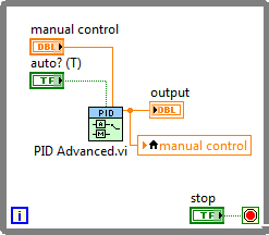
This VI cannot implement bumpless automatic-to-manual transfer. To ensure a smooth transition from automatic to manual control mode, you must design your application so that the manual output value matches the control output value at the time that the control mode switches from automatic to manual. You can do this by using a local variable for manual control, as shown in the following block diagram.
 Add to the block diagram
 Find on the palette


