FIR Narrowband Coefficients VI

Owning Palette: Advanced FIR Filtering VIs

Requires: Full Development System

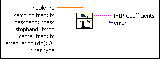
Generates a set of filter coefficients to implement a digital interpolated FIR (IFIR) filter.
Details  

 Add to the block diagram  Find on the palette
ripple: rp is the ripple in the passband of the filter. The default is 0.01.
sampling freq: fs is the sampling frequency and must be greater than zero. The default is 1.0. If sampling freq: fs is less than or equal to zero, the VI sets IFIR Coefficients to an empty cluster and returns an error.
passband: fpass is the passband bandwidth. The default is 0.01.
stopband: fstop is the stopband bandwidth. The default is 0.02.
center freq: fc is the center frequency of the filter. The default is 0.1.
attenuation (db): Ar is the attenuation in the stopband of the filter. The default is 60 decibels.
filter type specifies the passband of the filter.

0Lowpass (default)
1Highpass
2Bandpass
3Bandstop
IFIR Coefficients is a cluster that contains IFIR filter coefficients.
filter type is the filter type that you use to determine how to filter the data.

0Lowpass
1Highpass
2Bandpass
3Bandstop
4Wideband-Lowpass—For cutoff frequencies near Nyquist
5Wideband-Highpass—For cutoff frequencies near zero
interpolation is the interpolation factor M. The model filter is stretched by interpolation times.
Model Filter contains the coefficients of the model filter.
Image Suppressor contains the coefficients of the filter image suppressor.
error returns any error or warning from the VI. You can wire error to the Error Cluster From Error Code VI to convert the error code or warning into an error cluster.

FIR Narrowband Coefficients Details

The inputs to this VI cannot have negative values, and they cannot violate the Sampling Theorem.

The overall filter is a linear-phase FIR filter. This VI calculates the delay for the filter using the following equation:

where NG is the number of elements in the array Model Filter, NI is the number of elements in the array Image Suppressor, and M is the value of interpolation.

You can design narrowband FIR filters using the FIR Narrowband Coefficients VI, and then implement the filtering using the FIR Narrowband Filter VI. The design and implementation are separate operations, because many narrowband filters require long design times, whereas the actual filtering is very fast and efficient. Keep this in mind when creating your narrowband filtering diagrams.

Related Information

FIR Filters

FIR Narrowband Filter VI

Passband Ripple and Stopband Attenuation