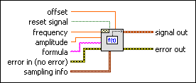
Formula Waveform VI
Owning Palette: Waveform Generation VIs
Requires: Full Development System
Creates an output waveform using a formula string to specify the time function to be used.

 Add to the block diagram Add to the block diagram |
 Find on the palette Find on the palette |
Owning Palette: Waveform Generation VIs
Requires: Full Development System
Creates an output waveform using a formula string to specify the time function to be used.

 Add to the block diagram Add to the block diagram |
 Find on the palette Find on the palette |
 |
offset is the DC offset of the signal. The default is 0.0. | ||||||||||||
 |
reset signal, if TRUE, resets the time stamp to zero. The default is FALSE. | ||||||||||||
 |
frequency is the frequency of the waveform in units of hertz. The default is 100. | ||||||||||||
 |
amplitude is the amplitude of the waveform. The amplitude is also the peak voltage. The default is 1.0. | ||||||||||||
 |
formula is the representation used to generate the signal out waveform. The default is sin(w*t)*sin(2*pi(1)*10). The following table lists the defined variable names.
|
||||||||||||
 |
error in describes error conditions that occur before this node runs. This input provides standard error in functionality. | ||||||||||||
 |
sampling info contains sampling information.
| ||||||||||||
 |
signal out is the generated waveform. | ||||||||||||
 |
error out contains error information. This output provides standard error out functionality. |
Formula Node and Expression Node Functions
Refer to the Waveform Generation Using Formula VI in the labview\examples\Signal Processing\Waveform Measurements directory for an example of using the Formula Waveform VI.