Basic Level Trigger Detection VI

Owning Palette: Waveform Monitoring VIs

Requires: Full Development System

Finds the first level-crossing location in a waveform. You can retrieve the trigger location as an index or as a time. The trigger conditions are specified in terms of threshold level, slope, and hysteresis. Wire data to the signal in input to determine the polymorphic instance to use or manually select the instance.

Note  Do not use the single-channel version of this VI for continuous multiple-channel processing.

Details  Example

Use the pull-down menu to select an instance of this VI.

 Add to the block diagram  Find on the palette

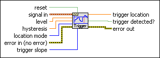
Trigger Detection for 1 Channel

reset specifies whether the history, or internal state, of the VI has to be reset. The default is FALSE. The internal state contains the final state of the input signal. The VI uses this as the initial state the next time LabVIEW calls the VI.
signal in contains the signal in which to detect a trigger.
level specifies the threshold value signal in must cross before a trigger is detected. The default is 0.
hysteresis specifies the amount above or below level through which signal in must pass before a trigger level crossing is detected. The default is 0.

Trigger hysteresis is used to prevent noise from causing a false trigger. For a rising edge trigger slope, the signal must pass below levelhysteresis before a trigger level crossing is detected. For a falling edge trigger slope, the signal must pass above level + hysteresis before a trigger level crossing is detected.
location mode specifies whether you want to retrieve the trigger location as an index into the Y-array of the waveform or as a point in time in seconds.

0Index (default)—Retrieves the trigger location in terms of an array index.
1Time—Retrieves the trigger location in terms of time in seconds. Time is computed by the following equation: time = t0 + (index*dt), where t0 and dt are contained in signal in. Use the To Time Stamp Function to convert this number to a time stamp data type with a time and date format.
error in describes error conditions that occur before this node runs. This input provides standard error in functionality.
trigger slope specifies whether a trigger is detected as signal in crosses level on a rising edge or a falling edge

0Falling Edge—The VI detects a trigger on the falling edge, or negative slope.
1Rising Edge (default)—The VI detects a trigger on the rising edge, or positive slope.
trigger location contains the index or time, depending on the location mode setting, of the detected trigger. If the location mode is in Time mode and you do not want the trigger location value to appear in seconds on the front panel, wire the trigger location to a time stamp.
trigger detected? indicates whether the VI detects a valid trigger. If trigger detected? is TRUE, the VI detects a valid trigger.
error out contains error information. This output provides standard error out functionality.

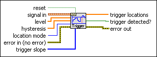
Trigger Detection for N Channel

reset specifies whether the history, or internal state, of the VI has to be reset. The default is FALSE. The internal state contains the final state of the input signal. The VI uses this as the initial state the next time LabVIEW calls the VI.
signal in contains the signals in which to detect triggers.
level specifies the threshold value that each signal contained in signal in must cross before a trigger is detected. The default is 0.
hysteresis specifies the amount above or below level through which each signal contained in signal in must pass before a trigger level crossing is detected. The default is 0.

Trigger hysteresis is used to prevent noise from causing a false trigger. For a rising edge slope, the signal must pass below levelhysteresis before a trigger level crossing is detected. For a falling edge slope, the signal must pass above level + hysteresis before a trigger level crossing is detected.
location mode specifies whether you want to retrieve the trigger location as an index into the Y-array of the waveform or as a point in time in seconds.

0Index (default)—Retrieves the trigger location in terms of an array index.
1Time—Retrieves the trigger location in terms of time in seconds. Time is computed by the following equation: time = t0 + (index*dt), where t0 and dt are contained in signal in. Use the To Time Stamp Function to convert this number to a time stamp data type with a time and date format.
error in describes error conditions that occur before this node runs. This input provides standard error in functionality.
trigger slope specifies whether a trigger is detected on a rising edge or a falling edge as each signal contained in signal in crosses level.

0Falling Edge—The VI detects a trigger on the falling edge, or negative slope.
1Rising Edge (default)—The VI detects a trigger on the rising edge, or positive slope.
trigger locations contain the index or time value, depending on the location mode setting, of the detected trigger for each waveform.
trigger detected? indicates whether the VI detects a valid trigger for each signal.
error out contains error information. This output provides standard error out functionality.

Basic Level Trigger Detection Details

This VI can perform single-channel measurements in both one-shot mode (single call) and continuous mode (multiple calls with history). It also can perform multichannel measurements in both one-shot mode and continuous mode. If you want to make multiple-channel measurements in continuous mode, you either must use the multichannel version of this VI or use one instance of this VI per channel. This VI detects only the first trigger for each channel.

The single-channel version of this VI is intended primarily for continuous processing of a single channel. Generalizing this behavior to the multichannel case, typically by using this single-channel VI in a For Loop to continuously process multiple channels by indexing an array of waveforms, is a misuse of this VI.

The single-channel version of this VI maintains internal state information for a single channel only. Calling this VI to process another channel without clearing the history, using reset or restart averaging, results in an unexpected behavior of this VI because the internal state information is passed from one channel to another.

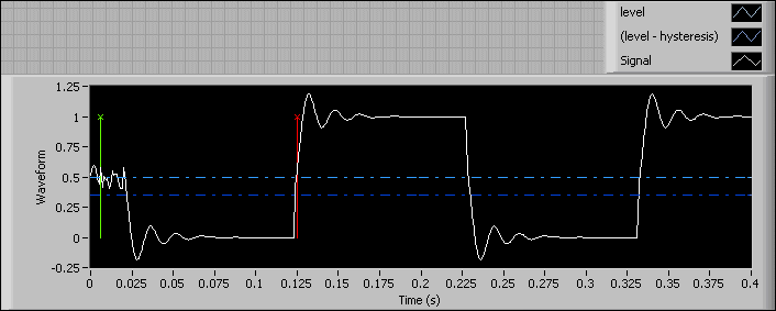
LabVIEW uses the hysteresis to prevent noise from causing a false trigger. For a rising edge slope, the signal must pass below levelhysteresis before a trigger level crossing is detected. For a falling edge slope, the signal must pass above level + hysteresis before a trigger level crossing is detected. The following graph shows how LabVIEW uses the hysteresis.

In the previous graph, the white line is the input signal. If the level is 0.5, and the hysteresis is 0.0, LabVIEW returns the green line that represents the false trigger caused by the noise. If the hysteresis is 0.15, LabVIEW returns the red line at approximately 0.125s that represents the valid trigger.

Example

Refer to the Basic Level Triggering of Waveforms VI in the labview\examples\Signal Processing\Waveform Measurements directory for an example of using the Basic Level Trigger Detection VI.

 Open example  Find related examples