Append Digital Signals VI

Owning Palette: Digital Waveform VIs and Functions

Requires: Base Development System

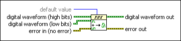
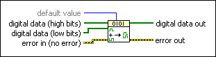
Appends the signals from digital waveform (low bits) to the LSB side of digital waveform (high bits). If the sampling rates do not match, error out returns a warning. The start time of digital waveform (low bits) is ignored. Wire data to the digital waveform (high bits) input to determine the polymorphic instance to use or manually select the instance.

Details  Example

Use the pull-down menu to select an instance of this VI.

 Add to the block diagram  Find on the palette

DWDT Append Digital Signals

default value specifies the value to use to fill in the extra samples of the digital data in digital waveform out if digital waveform (low bits) and digital waveform (high bits) do not have the same number of samples.

00 (default)—Force Down
11—Force Up
2Z—Force Z
3L—Compare Low
4H—Compare High
5X—Compare Don't Care
6T—Compare Invalid
7V—Compare Valid
digital waveform (high bits) is the first set of data in the digital waveform.
digital waveform (low bits) is the set of data to append to digital waveform (high bits).
error in describes error conditions that occur before this node runs. With the following exception, this input provides standard error in functionality.

This node runs normally even if an error occurred before this node runs.
digital waveform out returns the waveform that results from appending digital waveform (low bits) to digital waveform (high bits). This output matches the compression of the input.
error out contains error information. This output provides standard error out functionality.

DTbl Append Digital Signals

Appends signals of digital data B to the LSB side of digital data A. If the number of samples do not match, error out returns a warning. The number of signals do not have to be the same.

default value specifies the value to use to fill in the extra samples of the digital data in digital waveform out if digital waveform (low bits) and digital waveform (high bits) do not have the same number of samples.

00 (default)—Force Down
11—Force Up
2Z—Force Z
3L—Compare Low
4H—Compare High
5X—Compare Don't Care
6T—Compare Invalid
7V—Compare Valid
digital data (high bits) is the first set of data.
digital data (low bits) is the set of data to append to digital data (high bits).
error in describes error conditions that occur before this node runs. With the following exception, this input provides standard error in functionality.

This node runs normally even if an error occurred before this node runs.
digital data out returns the digital data that results from appending digital data (low bits) to digital data (high bits).
error out contains error information. This output provides standard error out functionality.

Append Digital Signals Details

Use the Append Digital Signals VI to append the signals from two separate digital waveforms into a single digital waveform. You can append signals with the same number of samples or of different numbers of samples. For example, if you have two digital signals that both consist of two rows of 8 bits, the resulting digital data consists of two rows of 16 bits. If you combine two signals, one that consists of two rows of 8 bits and the other that consists of one row of 8 bits, the resulting digital data consists of two rows of 16 bits. The Append Digital Signals VI pads the remaining columns in the second sample with the value you select in the default value input.

Example

Refer to the Append Digital Data By Signal VI in the labview\examples\Controls and Indicators\Graphs and Charts\Digital Waveform Graph directory for an example of using the Append Digital Signals VI.

 Open example  Find related examples