 |
compress digital specifies whether to compress the digital waveform or digital data. The default is TRUE.
|
 |
analog waveform is the waveform you want to convert to digital waveform or digital data.
|
 |
resolution specifies the number of bits represented in the digital waveform or digital data.
|
 |
full-scale range (pk-pk) specifies the total peak-to-peak range, or the difference between the minimum and maximum, for the digital waveform or digital data. For example, if the maximum range of a waveform is 1 and the minimum is –1, the full-scale range for the waveform is 2. The default is 2.
|
 |
error in describes error conditions that occur before this node runs. With the following exception, this input provides standard error in functionality.
If an error occurred before this node runs, this node outputs an empty waveform.
|
 |
data format specifies which binary representation you want to use for the digital waveform or digital data.
| 0 | unsigned binary—Converts the data to unsigned binary. | | 1 | offset binary (default)—The largest negative full-scale value is represented by all zeros, and the largest positive full-scale value is represented by all ones. Zero-scale is represented by a one (MSB) followed by all zeros, for example, binary 1000. | | 2 | 2's complement—Uses two's complement format, which is a common format for representing signed binary values. This format is similar to offset binary, but the MSB is inverted. |
|
 |
digital waveform returns the waveform that results from the conversion of analog waveform.
|
 |
resolution (out) returns the number of bits represented in the digital waveform or digital data.
|
 |
full-scale range (out) returns the total peak-to-peak range for the digital waveform or digital data.
|
 |
error out contains error information. This output provides standard error out functionality.
|
 |
compress digital specifies whether to compress the digital waveform or digital data. The default is TRUE.
|
 |
analog waveform is the waveform you want to convert to digital waveform or digital data.
|
 |
resolution specifies the number of bits represented in the digital waveform or digital data.
|
 |
full-scale range (pk-pk) specifies the total peak-to-peak range, or the difference between the minimum and maximum, for the digital waveform or digital data. For example, if the maximum range of a waveform is 1 and the minimum is –1, the full-scale range for the waveform is 2. The default is 2.
|
 |
error in describes error conditions that occur before this node runs. With the following exception, this input provides standard error in functionality.
If an error occurred before this node runs, this node outputs an empty waveform.
|
 |
data format specifies which binary representation you want to use for the digital waveform or digital data.
| 0 | unsigned binary—Converts the data to unsigned binary. | | 1 | offset binary (default)—The largest negative full-scale value is represented by all zeros, and the largest positive full-scale value is represented by all ones. Zero-scale is represented by a one (MSB) followed by all zeros, for example, binary 1000. | | 2 | 2's complement—Uses two's complement format, which is a common format for representing signed binary values. This format is similar to offset binary, but the MSB is inverted. |
|
 |
digital data returns the data resulting from the conversion of analog waveform.
|
 |
resolution (out) returns the number of bits represented in the digital waveform or digital data.
|
 |
full-scale range (out) returns the total peak-to-peak range for the digital waveform or digital data.
|
 |
error out contains error information. This output provides standard error out functionality.
|
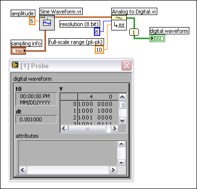
To create digital data from an analog waveform or to graph an analog signal in a digital waveform graph, you must convert the raw analog data into digital data or the digital waveform data type. Use the Analog to Digital VI to convert the data to digital waveform. Use the Get Waveform Components function to extract the digital data from the digital waveform.
The block diagram below simulates the acquisition of a sine wave with an amplitude of 5, which means the sine wave can contain values that range from –5 to 5. The Analog to Digital VI in this block diagram represents each value with 8 bits. The 8 bits can represent a peak-to-peak value of 10. The probe displays a portion of the resulting values in binary format.
 Add to the block diagram
 Find on the palette


