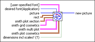
 |
[user-specified font] specifies the specific font characteristics for the text to draw. The VI ignores this input unless desired font is User-specified Font.
 |
Font Name specifies the font to use for the text. If you misspell the font name or specify a font that is not installed on the computer, the operating system selects a font.
|
 |
Size specifies the size of the font in points.
|
 |
Strikeout? specifies if the text appears in strikeout. If Strikeout? is TRUE, the text appears in strikeout.
|
 |
Italic? specifies if the text appears in italics. If Italic? is TRUE, the text appears in italics.
|
 |
Underline? specifies if the text is underlined. If Underline? is TRUE, the text appears underlined.
|
 |
Outline? specifies if the text is outlined. If Outline? is TRUE, the text appears outlined.
|
 |
Shadow? specifies if the text has a shadow. If Shadow? is TRUE, the text appears in shadow.
|
 |
Bold? specifies if the text is bold. If Bold? is TRUE, the text appears bold.
|
|
 |
desired font specifies the text font.
| 0 | User-specified Font | | 1 | Application Font (default) | | 2 | System Font | | 3 | Dialog Font |
|
 |
picture is the picture to which you want to add the plot. The default is an empty picture.
|
 |
rect contains the upper-left and lower-right coordinates that describe a rectangle bounding the text. The VI clips text to the coordinates of this rectangle. Horizontal coordinates increase to the right, and vertical coordinates increase to the bottom.
 |
left is the horizontal coordinate of the left edge of the rectangle.
|
 |
top is the vertical coordinate of the top edge of the rectangle.
|
 |
right is the horizontal coordinate of the right edge of the rectangle.
|
 |
bottom is the vertical coordinate of the bottom edge of the rectangle.
|
|
 |
smith plot section describes the portion of the graph you want to display. It contains four values that represent a rectangle superimposed over the Smith plot.
 |
x minimum is the smallest allowable value in the range of horizontal coordinates.
|
 |
x maximum is the largest allowable value in the range of horizontal coordinates.
|
 |
y minimum is the smallest allowable value in the range of vertical coordinates.
|
 |
y maximum is the largest allowable value in the range of vertical coordinates.
|
|
 |
smith grid cosmetics describes the style to use for the grids.
 |
R color specifies the color of the resistance, r, circles for the grids.
|
 |
R grids specifies to draw the resistance, r, circles for the grids.
|
 |
X color specifies the color of the reactance, x, circles for the grids.
|
 |
X grids specifies to draw the reactance, x, circles for the grids.
|
 |
Labels specifies to draw labels in the plot corners when you zoom in on a section of the plot.
|
|
 |
smith multi plot is an array of clusters, where each cluster contains an array of points. A point is represented by a cluster containing the r and x values that make up the complex impedance r + jx.
 |
smith plot is an array of points, where each point is a cluster containing the r and x values that make up the complex impedance, z, of r + jx.
 |
r is the resistance component of the complex impedance.
|
 |
x is the reactance component of the complex impedance.
|
|
|
 |
smith plot cosmetics specifies the style to use in drawing the plot.
 |
Plot Style is the style of plot to display. The default is a plot of lines and points.
|
 |
Line Color is the color of the line. The default in RGB is 0, 153, 255.
You can wire a color box constant to this input.
|
 |
Point Color is the color of the points. The default in RGB is 0, 153, 255.
You can wire a color box constant to this input.
|
|
 |
dimensions incl scales? indicates whether the rect input includes the scales, in addition to the plot area. If FALSE, the rect input describes the plot area, and the VI draws the scales outside of the rectangle. If TRUE, the VI draws the scales inside of rect and insets the plot area to make room for the text.
|
 |
new picture is the picture that contains the plot. You can wire this output to any other picture input to add more drawing instructions to the picture. You also can wire this output to the Picture to Pixmap VI to obtain an image data cluster. You then can save the image data to a file using the Graphics Formats VIs.
|

 Add to the block diagram
 Find on the palette


