Owning Palette: Scaling VIs
Requires: Base Development System
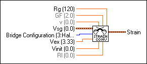
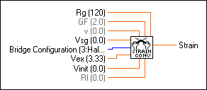
Converts a voltage read from a strain gauge to units of strain. Wire data to the Vsg input to determine the polymorphic instance to use or manually select the instance.
Use the pull-down menu to select an instance of this VI.
Add to the block diagram | Find on the palette |
Rg is the strain gauge nominal resistance value in ohms. The default is 120 Ω. | |||||||||||||||
GF is the gauge factor of the strain gauge. | |||||||||||||||
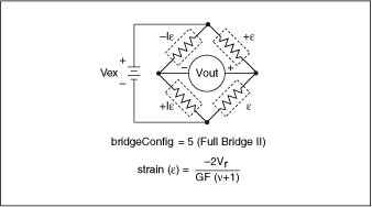
v is Poisson's Ratio. This parameter is only required for certain bridge configurations. | |||||||||||||||
Vsg is the voltage you read from the strain gauge. | |||||||||||||||
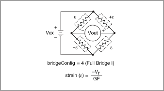
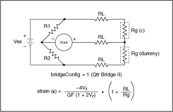
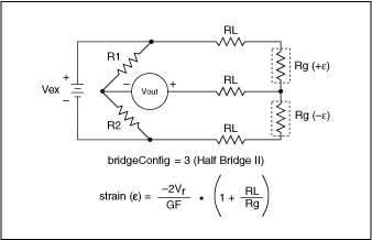
Bridge Configuration indicates the type of bridge configuration in which the strain gauge is mounted. The default is Half Bridge II. This input accepts the following values.
|
|||||||||||||||
Vex is the excitation voltage you use. The defaults is 3.333 V. | |||||||||||||||
Vinit is the unstrained voltage of the strain gauge after you mount it in its bridge configuration. Read this voltage at the beginning of your application and save it to pass to this VI. | |||||||||||||||
Rl is the lead resistance. The Rl parameter defaults to 0. In many cases, the lead resistance is negligible and you can leave this terminal unwired. | |||||||||||||||
Strain is the return strain value. |
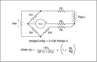
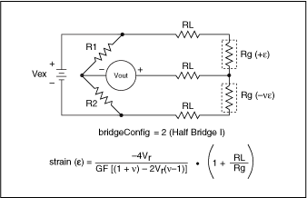
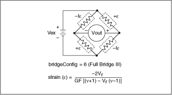
The conversion formula the VI uses is based solely on the bridge configuration. The following illustrations show the seven bridge configurations you can use and the corresponding formulas. For all bridge configurations, the VI uses the following formula to obtain Vr.
Vr= (Vsg – Vinit) / Vex
In the circuit diagrams, VOUT is the voltage you measure and pass to the conversion VI as the Vsg. In the quarter-bridge and half-bridge configurations, R1 and R2 are dummy resistors that are not directly incorporated into the conversion formula.
The following illustrations show the available bridge-completion networks.