Elliptic Coefficients VI

Owning Palette: Advanced IIR Filtering VIs

Requires: Full Development System

Generates the set of filter coefficients to implement a digital elliptic IIR filter.

You can pass these coefficients to the IIR Cascade Filter VI.
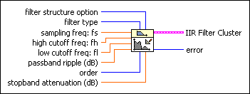
Details  

 Add to the block diagram  Find on the palette
filter structure option specifies the order of the IIR cascade filter in IIR Filter Cluster.

0IIR 2nd Order—Returns IIR second-order filter stages.
1IIR 4th Order—Returns IIR fourth-order filter stages.
2Auto Select (default)—Returns either IIR second-order or IIR fourth-order filter stages according to the filter type. If filter type is Lowpass or Highpass, this VI returns IIR second-order filter stages. If filter type is Bandpass or Bandstop, this VI returns IIR fourth-order filter stages.
filter type specifies the passband of the filter.

0Lowpass
1Highpass
2Bandpass
3Bandstop
sampling freq: fs is the sampling frequency in Hz and must be greater than zero. The default is 1.0 Hz. If sampling freq: fs is less than or equal to zero, the VI sets IIR Filter Cluster to an empty array and returns an error.
high cutoff freq: fh is the high cutoff frequency in Hz. The default is 0.45 Hz. The VI ignores this parameter when filter type is 0 (Lowpass) or 1 (Highpass). When filter type is 2 (Bandpass) or 3 (Bandstop), high cutoff freq: fh must be greater than low cutoff freq: fl and observe the Nyquist criterion.
low cutoff freq: fl is the low cutoff frequency in Hz and must observe the Nyquist criterion.

0 f1< 0.5fs

where f1 is the cutoff frequency, and fs is the sampling frequency. If low cutoff freq : fl is less than zero or greater than half the sampling frequency, the VI sets IIR Filter Cluster to an empty array and returns an error. The default is 0.125 Hz.
Note  All cutoff frequencies must be less than half fs.
passband ripple is the ripple in the passband. passband ripple must be greater than 0 and expressed in decibels. The default is 1.0. If passband ripple is less than or equal to 0, the VI sets the output filter data to 0 and returns an error.
order is the order of the IIR filter and must be greater than zero.
stopband attenuation is the attenuation in the stopband. stopband attenuation must be greater than zero and you must express it in decibels. The default is 60.0. If stopband attenuation is less than or equal to zero, the VI sets IIR Filter Cluster to an empty array and returns an error.
Note  If the filter order is high, this VI uses a higher attenuation than the value of stopband attenuation to design the filter.
IIR Filter Cluster contains the cascaded form of IIR filter coefficients.
filter structure indicates either IIR second-order or IIR fourth-order filter stages.
Reverse Coefficients is the reverse coefficients of the IIR cascade filter.
Forward Coefficients is the forward coefficients of the IIR cascade filter.
error returns any error or warning from the VI. You can wire error to the Error Cluster From Error Code VI to convert the error code or warning into an error cluster.

Elliptic Coefficients Details

The Elliptic Coefficients VI is a subVI of the Elliptic Filter VI.