 |
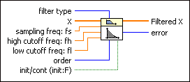
filter type specifies the passband of the filter.
| 0 | Lowpass | | 1 | Highpass | | 2 | Bandpass | | 3 | Bandstop |
|
 |
X is the input signal to filter.
|
 |
sampling freq: fs is the frequency in Hz at which you want to sample X and must be greater than 0. The default is 1.0 Hz. If sampling freq: fs is less than or equal to 0, this VI sets Filtered X to an empty array and returns an error.
|
 |
high cutoff freq: fh is the high cutoff frequency in Hz. The default is 0.45 Hz. The VI ignores this parameter when filter type is 0 (Lowpass) or 1 (Highpass). When filter type is 2 (Bandpass) or 3 (Bandstop), high cutoff freq: fh must be greater than low cutoff freq: fl and observe the Nyquist criterion.
|
 |
low cutoff freq: fl is the low cutoff frequency in Hz and must observe the Nyquist criterion. The default is 0.125 Hz. If low cutoff freq: fl is less than or equal to 0 or greater than half the value of sampling freq: fs, the VI sets Filtered X to an empty array and returns an error. When filter type is 2 (Bandpass) or 3 (Bandstop), low cutoff freq: fl must be less than high cutoff freq: fh.
|
 |
order specifies the filter order and must be greater than 0. The default is 2. If order is less than or equal to 0, the VI sets Filtered X to an empty array and returns an error.
|
 |
init/cont controls the initialization of the internal states. The default is FALSE. The first time this VI runs or if init/cont is FALSE, LabVIEW initializes the internal states to 0. If init/cont is TRUE, LabVIEW initializes the internal states to the final states from the previous call to this instance of this VI. To process a large data sequence that consists of smaller blocks, set this input to FALSE for the first block and to TRUE for continuous filtering of all remaining blocks.
|
 |
Filtered X is the output array of filtered samples.
|
 |
error returns any error or warning from the VI. You can wire error to the Error Cluster From Error Code VI to convert the error code or warning into an error cluster.
|
 |
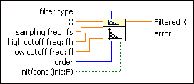
filter type specifies the passband of the filter.
| 0 | Lowpass | | 1 | Highpass | | 2 | Bandpass | | 3 | Bandstop |
|
 |
X is the input signal to filter.
|
 |
sampling freq: fs is the frequency in Hz at which you want to sample X and must be greater than 0. The default is 1.0 Hz. If sampling freq: fs is less than or equal to 0, this VI sets Filtered X to an empty array and returns an error.
|
 |
high cutoff freq: fh is the high cutoff frequency in Hz. The default is 0.45 Hz. The VI ignores this parameter when filter type is 0 (Lowpass) or 1 (Highpass). When filter type is 2 (Bandpass) or 3 (Bandstop), high cutoff freq: fh must be greater than low cutoff freq: fl and observe the Nyquist criterion.
|
 |
low cutoff freq: fl is the low cutoff frequency in Hz and must observe the Nyquist criterion. The default is 0.125 Hz. If low cutoff freq: fl is less than or equal to 0 or greater than half the value of sampling freq: fs, the VI sets Filtered X to an empty array and returns an error. When filter type is 2 (Bandpass) or 3 (Bandstop), low cutoff freq: fl must be less than high cutoff freq: fh.
|
 |
order specifies the filter order and must be greater than 0. The default is 2. If order is less than or equal to 0, the VI sets Filtered X to an empty array and returns an error.
|
 |
init/cont controls the initialization of the internal states. The default is FALSE. The first time this VI runs or if init/cont is FALSE, LabVIEW initializes the internal states to 0. If init/cont is TRUE, LabVIEW initializes the internal states to the final states from the previous call to this instance of this VI. To process a large data sequence that consists of smaller blocks, set this input to FALSE for the first block and to TRUE for continuous filtering of all remaining blocks.
|
 |
Filtered X is the output array of filtered samples.
|
 |
error returns any error or warning from the VI. You can wire error to the Error Cluster From Error Code VI to convert the error code or warning into an error cluster.
|
 Add to the block diagram
 Find on the palette


