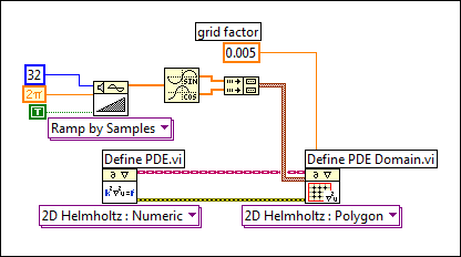
Define PDE Domain VI
Owning Palette: Partial Differential Equations VIs
Requires: Full Development System
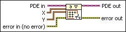
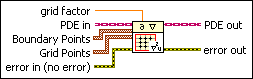
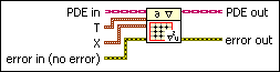
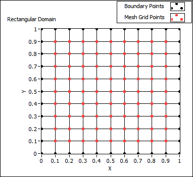
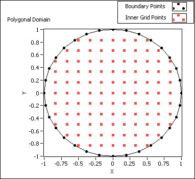
Defines the domain where you solve the partial differential equation. You must manually select the polymorphic instance to use.
Use the pull-down menu to select an instance of this VI.
 Add to the block diagram Add to the block diagram |
 Find on the palette Find on the palette |